Wednesday, December 11, 2013

Reflections

See a summary of our cosmic 2.008 journey in our final video HERE!

Cost Analysis

Cost per yoyo (prototyping 100): $28.21

Cost per yoyo (manufacturing 100,000): $1.92
These numbers were calculated according to the Ashby Cost Model, which includes material, equipment, tooling, and overhead costs.  However, we overlooked the cost of student labor in our calculations.  


Materials:


m = part mass (0.086 kg)
Cm = material cost ($3.9/kg)
f = waste fraction (0.2)

Tooling:


Ct = tool cost [$/tool]
nt = tool lifetime [parts]
n = total runs [parts]

Machinery: 


n = production rate (0.2 parts/min)
Cc = equipment cost ($500,000)
L = load factor (0.9)
t = lifetime (10 years)


Overhead:


Coh = overhead costs, energy, labor, etc ($50/hr)
n = production rate (60 parts/hr)

In the cost analysis, we accounted for mold manufacturing, cost of resin pellets for injection molding, polystyrene thermoform material, axle sleeves and hex nuts, design labor, staff labor, and machine production run time.  As the number of parts manufactured increases, the cost per yoyo decays, as seen below: 

Cost per Yoyo [$] vs Number of Yoyos Manufactured
# Yoyos Produced

Mass Production

In adapting our design for mass production, we might make fewer sacrifices in terms of color.  We would have liked more time to experiment with colors for our yoyo parts, especially the ring and body.  For example, when producing the body, we experimented with marbling but eventually stuck with pure black due to time constraints.  With more injection molding machines for mass production, however, we would be able to vary colors of our yoyo parts more easily and be able to offer customers more options for space yoyos without worrying about the crunch for time that comes with having to flush out previous colors from the injector.   

The molds would have to be made out of a more robust material like steel in order to withstand more production runs.  Additionally, we would redesign our molds to produce perhaps hundreds of the same part of the time.  This might involve redesign of the injection molded parts to adapt for the necessary runners between parts.  Our themoforming process would be unsustainable in mass production.  We would need a rollfeed system into the thermoform machine and then an automatic punch.  To further increase cycle time, we might think of using a thinner polystyrene sheet in the thermoforming process.  This would require redesign in the injection molded moon and star disc and the moon and star thermoform part to adjust the affected dimensions.

Course Reflections

Our favorite parts of 2.008 were the interactive components of the lectures and our time working in the lab.  Applying knowledge from lecture material to in-class examples with small teams was a great way to quickly grasp the concepts of the material.  Additionally, the in-class demonstrations put on by Dave and Dave were really interesting and much appreciated.  Having access to and being trained on the neat manufacturing machines in the lab was great.  Hands-on experience, making molds, optimizing production runs, and cranking out yoyos was fun and extremely useful for learning about industrial fabrication processes.  With the relatively large size of the teams, it could be possible to squeeze another type of manufacturing process into the requirements for the yoyo design in addition to injection molding and thermoforming. 

In terms of the class structure, we felt the lectures were often long and over-stuffed.  A structure with Monday/Wednesday/Friday lectures one hour long could be nicer.  Additionally, we covered so many interesting topics within manufacturing that for some parts it would have been nice to choose fewer so as to delve deeper into the subject material.  This could be done more smoothly in accordance with the lab assignments, relating the lectures to the yoyo project more tightly.  The reading quizzes were very good (we actually did the readings!) but not very fun to have every lecture.  And the readings were usually great preparation for the lectures, especially the textbook readings.  The research articles towards the end of the semester seemed too complex and unnecessarily stressful for the scope of the lectures and reading quizzes that followed them.

Turning in blog assignments was a fun addition to the course structure, as was the poster session - a nice wrap-up and celebration.  This has been a great class.  Thank you to Professors Hart and Culpepper and Sanha Kim for the semester.  We are so proud of what we were able to accomplish!  We felt very well-prepared for the yoyo project and appreciate the great lab instruction - thank you Dave and Dave!  


Friday, December 6, 2013

The Final Product!


Individual Parts

The yoyo body is shown below.  The key feature of this part is the inner diameter, as this is crucial for the snap fit with the green ring.  We're very happy with the radius we added to the outside rim.  Reducing the sharpness of this edge makes catching the yoyo much more comfortable.  One opportunity for improvement lies in the coloring of the body.  We would have liked to experiment more with marbling black and silver.  The majority of these parts are pure black, which is still nice because it connects with the black inside moon and star disc. 

The first part to be added to the body in the assembly is this white moon and star thermoform part.  The key features on this part are the outer dimensions of the moon and star since this piece has to fit into the injection molded moon and star disc.  The texture on this part turned out perfectly!  We are especially excited about how the craters on the moon turned out.  Also, the stripes on the comet tail were a later addition and we're really glad we added that detail.  An opportunity for improvement on this part is in the tiny webbing we were still unable to eliminate between the star and comet tail, although this didn't interfere with the fit into the injection molded disc.


Next to be added to the assembly is the injection molded moon and star disc.  The key parameters on this part are the inner dimensions of the moon and star so as to fit nicely over the white thermoformed part above.  These dimensions fit extremely nicely - the thermoformed part snaps beautifully into the part without gaps.  The black and white contrast without gaps really brings out the texture of the moon and star.  One thing to improve on this part is on the outer diameter - the part did not shrink as much as expected and so does not slide into the body as well as hoped, but this tighter fit is not a problem in our assembly.


Then we place a laser-cut acrylic rocket on top of the moon and star layer.  The rocket 'flies' loose around the yoyo, trapped by the window.  A key feature is the thickness of the acrylic since we wanted the rocket not to be able to slide between the window and surface below.  We chose 0.11" acrylic for the job according to the window dimension.  We are really happy with the material colors we chose for this part.  We decided to make the rocket colors asymmetrical, one transparent red rocket and another mirror rocket on the other yoyo half.  A potential point of improvement for these parts is gluing them down.  We will do this with a small fraction of the yoyos, but based on feel, the small change in moment of inertia has no significant effect on the rotation of the yoyo.


Next, we place the window into the assembly.  The key dimension here is the window diameter, since it needs to fit inside the ring.  The windows turned out really nicely - they are very clear, without many bubbles, not obstructing the inside view of space.  The optimization for reducing bubbles on the surface of the window was pretty tedious and we ended up blowing air on the plastic before every run in order to clear bubble-causing dust. 


The last piece of the assembly process is the ring.  This piece really holds everything together.  The snap fit between the inner diameter of the body and outer diameter of the ring is crucial.  This parameter turned out well, and the ring has a great fit between the body and window.   We are so happy with the color we were able to get.  The bright green really brings some pop and brightens the yoyo which is otherwise black and white.  We experimented with the color a lot, first trying a marbling with glow-in-the-dark then with black, but never getting satisfactory results.  Also, doing a run on the black moon and star discs prior to this made flushing the black out of the green really difficult resulting in some putrid greens.  You can see the evolution in the second picture below!


 And finally...the assembled product! 


Meeting Design Specifications

Below are histograms which show control limits and the measured critical dimension for each part.


Yo-Yo Body: Inner Diameter target dimension = 2.000in(+0.000in/-0.010in)
Almost all of our parts had a larger diameter than our target range. This was most likely because the effect of shrinkage was not as great as we estimated it to be. However, during our optimization runs the parts fit perfectly with the rings, so we did not make any changes. We did not have any problems with the snapfits during our final assembly. 


Thermoform moon and stars piece: target dimension for distance from opposite edges of moon: 0.092in


Injection molded moon and stars piece: thickness target dimension = 0.108in
We were within our tolerances for this part. There were no critical dimensions other than making sure it fit with the thermoform part. 


Ring: Outer Diameter Target = 2.000in (+0.010in/-0.000in)
Several parts were outside of our tolerance range, possibly due to improper prediction of shrinkage. However, this did not affect our final assembly, as there were no problems getting the rings to snapfit into the yo-yo.

Window: Outer Diameter  = 1.800in
While almost all parts were smaller than the target dimension, this was acceptable because the critical factor was that the window was able to fit inside the ring.


String gap: Target dimension = 0.075in
Our string gaps were much larger than our target. This could be due to placement of the nut inside the body, and how tightly we screwed the shafts in during assembly. We also noticed that body parts that had 2 colors had a smaller string gap.  Our yo-yo works fine despite the deviance from our intended design.


Findings: Injection Molded Moon and Star Part
 
The target value for the thickness of the injection molded moon and star part was 0.108".  The mean value of the 100 parts made was 0.10778".  According to the Shewhart X-bar chart, the majority of our parts were within the upper and lower control limits, with only a few exhibiting more or less shrinkage due to disturbances in cooling times. 
There was less shrinkage in the injection molding process for this part than expected.  Initially, we had accounted for 8% shrinkage with a target value of 0.1" but when it was found that the parts that did not shrink as much fit better into the yoyo assembly, the target value of this part was changed to 0.108" for the production runs.        
In summary, the production run responded as was expected to disturbances in cooling times, resulted in a set of 100 parts which were all usable despite a minority which were a little bit out of specification, and resulted in a good process capability of 0.490 and relatively small standard deviation of 0.003".   Scrolling to the bottom of the link below will lead you to the run chart, histogram, and Shewhart x-bar chart for the injection molded moon and star part:

Paper Deliverable 4

Monday, November 18, 2013

Optimization

Injection Molded Disc Optimization:

In the last post, we talked about the mold for the injection molded disc with moon and star cut-outs.  The injection molding process for this part of our yoyo was optimized through experimenting with cooling times, feed strokes, and injection boost pressures.

Below is the data collected throughout the process optimization.  After changing parameters, a few parts for each trial were  manufactured and diameters and thicknesses at various points were measured.  Additionally, we looked for flash in the windows.

MOON AND STAR INJECTION MOLDED PART OPTIMIZATION
Trial # Cool Time (s) Feed Stroke (in) Inj. Boost Pressure (psi) Diameter 1 (in) Diameter 2 (in) Thickness 1 (in) Thickness 2 (in) Flash
1 17 1.1 1600 2.016 2.023 0.108 0.108 tiny bit 
" " " 2.015 2.019 0.107 0.107 "
" " " 2.015 2.014 0.107 0.106 "
2 17 1 1600 2.017 2.016 0.103 0.107 "
3 15 1 1400 2.013 2.011 0.107 0.106 "
" " " 2.015 2.015 0.107 0.107 "
4 10 1 1400 2.015 2.017 0.107 0.108 none
" " " 2.012 2.018 0.105 0.107 "
5 12 1 1400 2.014 2.016 0.107 0.107 "
" " " 2.011 2.013 0.107 0.107 "

The injection boost pressure was lowered in an attempt to effect the flash we were getting in the disc windows.  Lowering the pressure reduced flash. 
Cooling times were altered to experiment with effects in shrinkage.  Part measurements were taken the day after manufacturing and had time to completely cool.  Parts with less cooling time would shrink more than parts manufactured with longer cooling time.
Having flash is undesirable aesthetically and also in terms of tolerances in fitting the moon and star thermoformed piece through the windows, so all trials in which flash existed were eliminated.   Next, we looked at the average of the two diameter measurements for each part manufactured.  Since the disc diameter is a more critical assembly parameter than the thickness, we eliminated first on the basis of out-of-spec diameter.  While overall the percent shrinkage we accounted for in the mold design was too large (our target diameter is 2 inches), the discs fit into the body well.  We took the lowest average diameters, though, in order to stay in spec as best as possible. 

The conditions of Trial #5 won out in the end, had our first production run, and have 100 beautiful moon and star discs now!


Optimization of Other Yo-yo Parts:
Yo-yo Body:
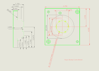
The cooling time was changed during the optimization runs for the body to experiment with the effects of shrinkage. Our optimized cooling time is 25 seconds. The body mold was edited to remove the sharp edge on the outside diameter. Updated drawing:


Thermoformed Parts - Window, Moon and Star Insert:
The thermoformed parts did not need redesign, but both molds needed remachining so they fit the original  drawing specs. The window mold had nicks around the edge so a completely new mold was made, and lapped on the top surface. The moon and stars mold was machined incorrectly so the mold was remachined to match the drawings. The optimization focused on finish for the window parts and reduction of webbing on the moon and stars part.

Sunday, October 20, 2013

Mold Design and Manufacturing Analysis


The moon and stars design of the yoyo is made up of two parts, one injection molded and one thermoformed.  The black injection molded part is meant to frame the white thermoformed part such that white moon and star are visible through the injection molded piece.  Below are the molds for the injection molded moon and star part, core mold on the left and cavity mold on the right.


The cavity mold defines the outer shape and thickness of the part and is complete with sprue and runner. The more complex core mold is shown below in more detail and has four ejector pin holes for  removal of the part from the mold.  This core mold will create the moon and star-shaped stencils in the part, through which the thermoform part will fit.


These molds were scaled in order to account for inherent shrinkage in the injection molding process.  To determine a reasonable scaling factor, a similar injection molded piece found in the lab was measured with digital calipers eight times each for three different features on different iterations of the part.  The same features were measured on the molds and then percent shrinkages were calculated with the averaged eight measurements of the parts.  For example, the average measured disc thickness was 0.147813 mm while the thickness imposed by the mold was 0.149 mm.  This comes out to a percent shrinkage of 0.803382664.  Therefore, since the goal thickness for our injection molded part is 0.1 mm, the molds were designed with a 0.108 mm thickness in mind to compensate for shrinkage.

Manufacturing Process:The cavity and core molds were both manufactured entirely on the mill, with the cavity mold taking approximately two minutes to complete and the more complex core mold taking around one hour to finish.  To begin with, the mold blanks were faced in order to ensure the tops of the islands on the core  mold would be flush with the bottom of the cavity mold.  After the milling process, the ejector pin holes and sprue were reamed.  Below are the process plans for each mold, detailing operations and tool changes. 

Cavity Mold:

Step
Operation
Machine
Tool
Justification
1
Facing
Mill
7
Faces surface of the cavity mold blank.
2
Pocket (Standard)
Mill
7
Removes material in center of piece, depth of .108”
3
Contour (2D)
Mill
9
Creates the runner at a depth of 0.09”


 Core Mold:

Step
Operation
Machine
Tool
Justification
1
Facing
Mill
12
Faces top surface so top of islands will fit perfectly with bottom of cavity mold
2
Drill/Cbore
Mill
13
Center drills for the 4 ejector pin sites.
3
Peck Drill
Mill
17
Creates the through- holes for the four ejector pins.
4
Pocket (Facing)
Mill
5
Faces surface of the core mold blank, leaving a buffer distance around the island.
5
Pocket (Remachining)
Mill
1
Removes closer to the island, creating finer details.


Manufacturing time estimates:
Mold Machining time:
Part
Machining time (min)
Optimization
Final production run
Body Cavity Mold
3
Production runs: 38min
Remachining: 5min
110min
Body Core Mold
4
Thermoform M&S insert
35
Production runs: 30min
Remachining: 20min
70min
M&S core mold
48
Production runs: 18min
Remachining: 20min
50min
M&S cavity mold
27
Thermoform Window mold
2
Production runs: 30min
Remachining: 2min
70min
Ring core mold
4
Production runs: 30min
Remachining: 3min
85min
Ring cavity mold
2

Total mill/lathe time: 125min
Total Injection mold machine time:  245min
Total Thermoform machine time:  140min

For the process of optimization, it is estimated that 4 production runs of 8 parts will be made. The amount of time to produce one part was estimated based on the part thickness. The components of a cycle of injection molding include mold closure, injection, pack and hold, part cooling, mold opening, and ejection. The driving component of total injection molding time is the cooling time needed.  This was estimated using the formula T_cool = h^2/4α and the material properties of ABS (we were unsure what material will actually be used). For example, the cooling time for the yo-yo body was estimated to be ~45 seconds, and total part production time ~1 minute and 5 seconds (20 seconds for all other components of injection molding process).

For thermoforming it was assumed that the HIPS would take about 30 seconds to heat up and would freeze upon contact. The remachining time for the optimization process was estimated based on the complexity of the mold – e.g. whether it would only be necessary to turn the part to a slightly smaller diameter, or if it might be necessary to redo detailed engraving work.

For the final production run, the time to make one part was multiplied by the 100 of each part needed.
It was decided that the rocket will be no longer be injection molded. Instead it will be laser cut from acrylic, which will take about an hour.


Here is the cavity of the mold for the Space Yo-yo's body. The outer diameter of the upper part of the cavity is expected to be reworked to account for excess shrinkage in the part. This is to make sure that the outer diameter of the space yo-yo matches the expected 2.5".


The dimensions of the body core mold (above) were increased from the original drawings due to the desire for a thinner yo-yo body. The slight burrs left on the top edge were removed with a file to prevent the possibility of that slight undercut affecting the ease with which the finished part can be ejected. The outer diameter of the core is expected to be modified based on shrinkage form.


The ring cavity mold consists of a circular cavity with the outer diameter of the ring and three runners. The top runner leads to the sprue while the remaining runners lead to ejector pin holes located on the core mold. These runners might need rework so as to ensure that there is enough material for the ejector pins to push on. This will ensure that the workpiece is ejected successfully.


The ring core mold consists of a circular island with an inner diameter slightly larger than that of the inner window. The mold has two holes set a distance away from the island, which are for the ejector pins, which will come into contact with the runners on the cavity mold to help remove the ring from the mold. The diameter of the cavity may need to be modified/decreased in order to make sure that the thermoformed window fits inside of the ring, but it is not a critical dimension.


This is a thermoform mold, minus the suction holes and punch guides which have been added since this picture was taken. There may be webbing on the parts this makes between the star and its trail, so more suction holes may have to be added.


This is the completed mold for the thermoformed yo-yo window. The top surface of the mold (which corresponds to the top of the window) was machined at a slower feed rate than the rest of the part for a higher-quality surface finish, which should be reflected in the thermoformed parts. The alignment pins (the two posts on the edges of the material) will act as guides for the punch. Suction holes (very small circle, front center of the part), which were created using a #68 drill bit, should help ensure that the vacuum pulls the plastic sheet into the correct shape. Since this part does not have any critical dimensions, we are not anticipating needing to rework this part.